Just got my Google Profile URL:
http://google.com/+jameswolf
Pretty cool.
Just got my Google Profile URL:
http://google.com/+jameswolf
Pretty cool.
Added new Photo Booth page showing current prototype

Photo-Booth for the wedding, pics and explanation video of hardware used
Using the milli() function in order to do accurate timing on the Arduino doesn’t work because it shares the same priority in code execution as any other code. I wrote a blog post that talks about using PWM and an interrupt in order to create a much more accurate clock. In my post I talk about how to wire the PWM to the interrupt and how to use the Adafruit 2.2 inch TFT LCD to display the time. The full post with pics, links and demo code is here:
https://contractorwolf.wordpress.com/arduino-pwm-interrupt-clock/
I also recorded a video of it in action:
My plan here is to use the $9 Arduino Nano and the Roving Networks RN-171 serial wifi to make a wifi enabled sensor that can post to the cloud. First step i had to do was solder some legs on the smd wifi chip. These pads are small but you can see in the pictures that i have 4 legs now: tx, rx, gnd and 3.3v.


I put this new setup on a breadboard so that i could reconfigure the pins as needed. I like this sort of “dead-bug” construction.

Next up I have to communicate over serial with the part and has a lot of questions about the best way to do it. For now I am toing to use my FTDI Basic USB from sparkfun.com and teraterm at 9600 (from the user guide). Ill let you know how it goes.
Also me demo’ing on the Adafruit.com “Show & Tell” with Amanda and Limor from Adafruit:
I start at the halfway point on the video
My latest demo video of the IR Cam Headtracker:
This is actually not the latest version of the controller software. I have made a few revisions since posting this on youtube that eliminates some of the jerky movements and gets rid of all the mismatched Bytes (coming from the camera). The end results is a lot smoother than you see here. Right now I am working on putting the Max Power IR LED’s into the headset in the hopes that I can extend the distance between the headset and the camer (right now my max distance is ~1 meter, and i need it to work as well at 2 meteres for larger TV’s).
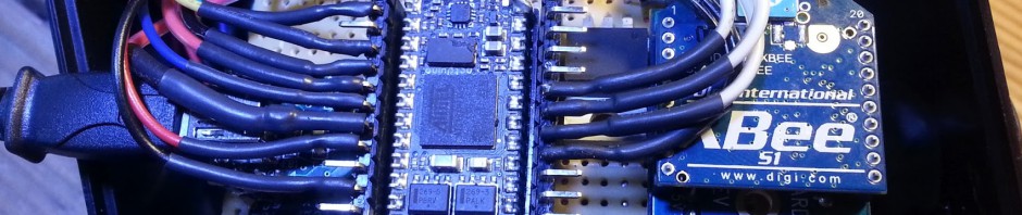
I finally got a chance to solder the rest of what I am calling my “Enigma” board. It is basically a Netduino mini with USB for both power and debugging, and Xbee for communication. I made it as the receiver for my headtracking camera data but paid special attention to make it flexible enough to use on many other projects.
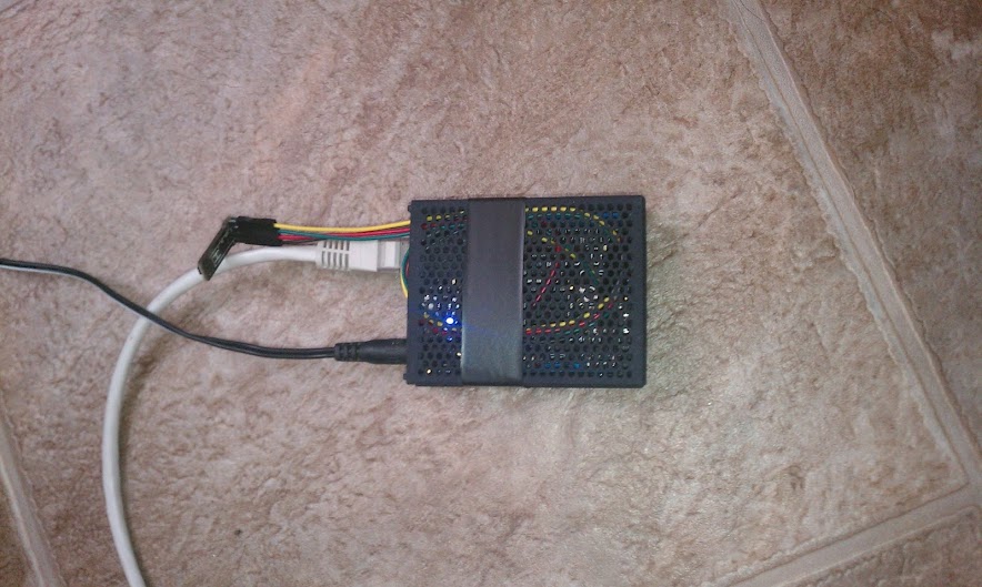
Here it is plugged into an enercell battery pack for power:

I wanted to make sure I paid a lot of attention to the design so I could do it on a single board (perf board from radio shack) with only one side as pcb traces (done in careful solder) and no other wires. It is bascially the same size as the netduinos but it has xbee. It could also do wifi since they make Xbee wifi modules that use the same form factor. The other components on the board are the Xbee, a MAX232 (for translating the rs232 to TTL for the Xbee), a UB232R USB fdti chip for doing USB power and debugging, and a LM1117 3.3v regulator for the Xbee power.
Here is the bottom of the board so you can see how I got away with no wires on the top:

It may seem like a lot of work, but the truth is the design part is now done so I can easily make more. I think I will do an eagle file and make some easy PCB’s next and see if anyone likes them. That is right after I finish the headtracking bit, ah so much left to do… 🙂

Ive been reading the Getting Started with the Internet of Things as I learned to use the Netduinos. They are really great, the minis are super small and the Netduino Plus has the Cat-5 Jack, so it has simple web interaction basically built in. I say “simple” because if you understand some of what HTTP is, and think about this as a micro device, this becomes powerful.
This is what the device looks like:
Right now I have the Netduino set to send an HTTP PUT to my Pachube.com feed. Pachube is a simple service setup for microcontrollers. Its a great free service (as long as your posts dont happen faster than their reasonable 12 second limit) as well having a decent API, it can even post to Twitter. I set up the feed in basically 1 minute, and it only has 2 parts: humidity and the temperature.
You can see the feed in full here: Pachube.com Feed 50487
The graph here (also show at the top) is the actual graphing of the humidity detected by the sensor and reported to pachube over the last hour (every 20 seconds):
