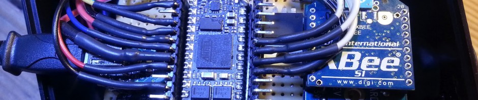
I finally got a chance to solder the rest of what I am calling my “Enigma” board. It is basically a Netduino mini with USB for both power and debugging, and Xbee for communication. I made it as the receiver for my headtracking camera data but paid special attention to make it flexible enough to use on many other projects.
Here it is plugged into an enercell battery pack for power:

I wanted to make sure I paid a lot of attention to the design so I could do it on a single board (perf board from radio shack) with only one side as pcb traces (done in careful solder) and no other wires. It is bascially the same size as the netduinos but it has xbee. It could also do wifi since they make Xbee wifi modules that use the same form factor. The other components on the board are the Xbee, a MAX232 (for translating the rs232 to TTL for the Xbee), a UB232R USB fdti chip for doing USB power and debugging, and a LM1117 3.3v regulator for the Xbee power.
Here is the bottom of the board so you can see how I got away with no wires on the top:

It may seem like a lot of work, but the truth is the design part is now done so I can easily make more. I think I will do an eagle file and make some easy PCB’s next and see if anyone likes them. That is right after I finish the headtracking bit, ah so much left to do… 🙂

I love your 5V powerbank and I never thought of soldering the pads together on the perf board ( I always use wires and looks very nice and clean on top, but on the bottom… nobody have to see that). You have great projects. thanks for your time to share them with us.
Thanks cry4brk, I like to do them this way because it makes it very obvious what parts are connected. Sometimes its takes a little more time to lay it out but its worth it for the final clean look. Plus when I can figure out a way like this its super easy to order a single sided PCB that just follows the same pattern. The protoboards with the square pads from Radioshack are the best to use like this, and I usually help connect the pads using cut legs from resistors or other similar wire.