| UPDATE: See the module posting temperature updates in real time using a DS18B20 temperature sensor. |  |
A few months ago a new board called the ESP8266 arrived on the scene and promised a very cheap way for serial devices (such as the Arduino) to to make HTTP requests. The device itself was less than $10 (I got a few on AliExpress for $5) and it meant that smart microcontrollers could be easily made into “Internet of Things” devices.
The boards (from the factory) operate at 115200, and that is just too fast for SoftwareSerial, so I decided to use and Arduino Micro to play around with it. The Arduino Micro has two serial ports so that it can communicate over USB (for debugging) as well as communicate over another serial channel (Serial1). This mean that I could use the Arduino Micro as a serial pass-through device and communicate with the ESP8266 directly.
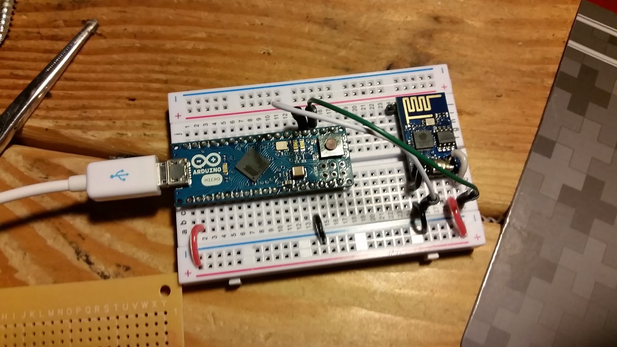
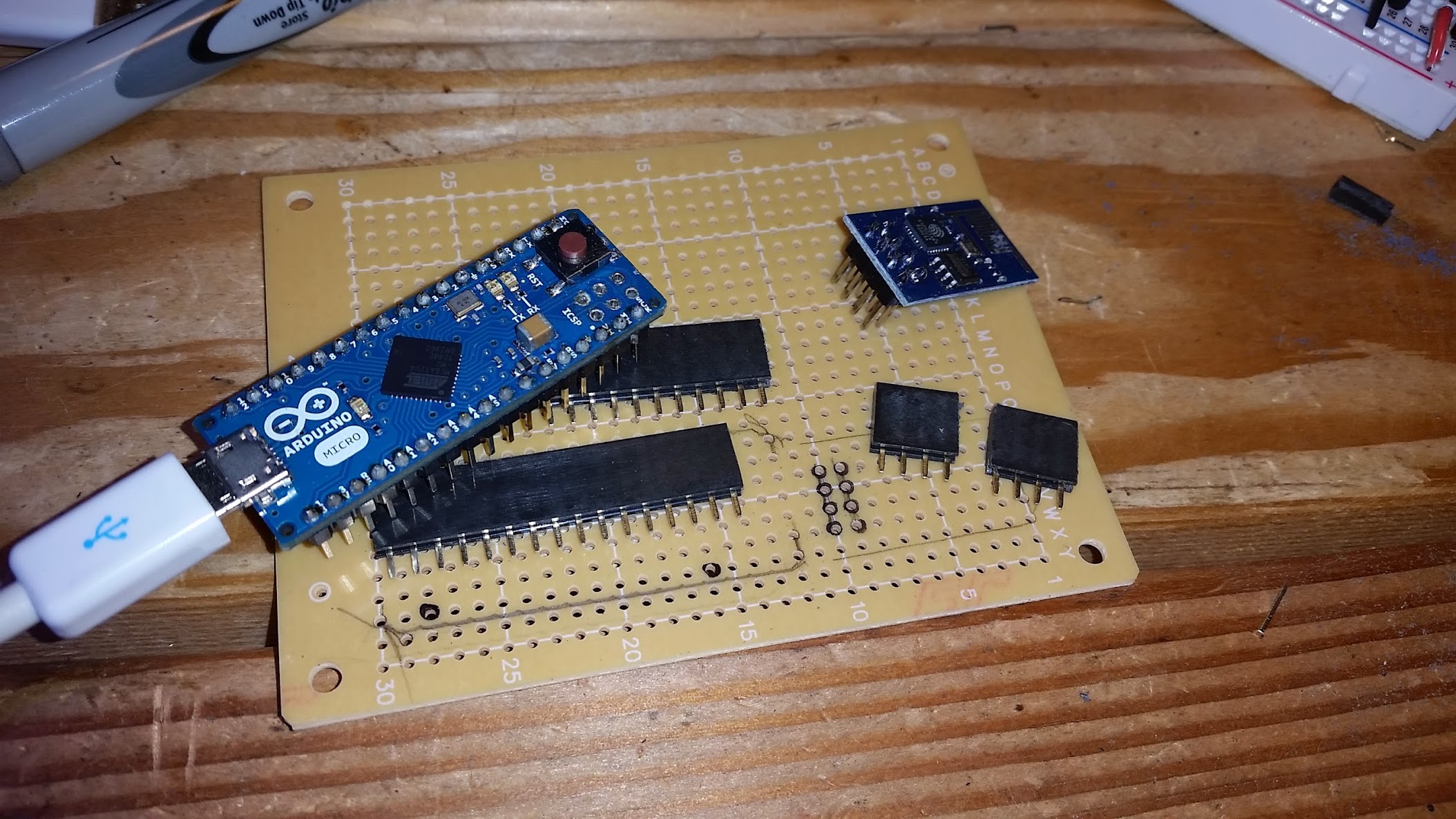
The annoying part was the 8 pin setup was not very breadboard friendly, so I de-soldered the back row of pins (GND, GPIO1, GPIO2, RX) and attached external wires so that they would work easier on a breadboard. This is what it looked like when it was first setup:
After first getting it responding to commands over serial, I decided that what I needed to do was get the device able to connect to my Wifi and make simple HTTP requests. Being able to make HTTP requests (to me) is the heart of IOT (Internet of Things). I quickly found out that I first needed to switch the Mode using the following commands:
AT+CWMODE=1
then reset the board
AT+RST
then connect to your wifi
AT+CWJAP=”YOUR_WIFI_NETWORK”,”YOUR_WIFI_PASSWORD”
The next step is a little more complicated using serial, because it needs to know the length of your total request in order to make the full request. It actually gets broken up into 2 parts, 1) the connection to the server, and 2) the actual GET request.
send commands (note: replace anything in {} below with real values):
AT+CIPSTART=”TCP”,”{domain}”, 80
AT+CIPSEND={length of GET request string below}
{wait for “>” string to be returned by ESP8266}
GET http://{domain + path} HTTP/1.0\r\n\r\n
I put these 2 commands into a single method so that I could just pass it the URL, and it would extract the domain and the path in order to generate both AT command.
I created a public GitHub repo to hold the code I am currently using. The code attempts to autoconnect to your home network and then allows you to pass it either an AT command for controlling the ESP8266 or a URL to download. The file is located here:
https://github.com/contractorwolf/ESP8266
Making a board to connect the Arduino Micro and the ESP8266
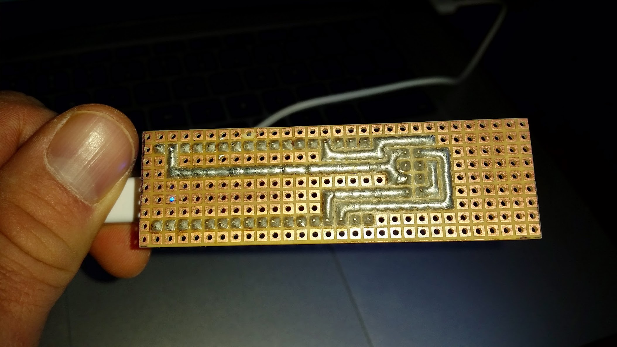
I wanted a nice clean way to attach the ESP8266 to the Arduino Micro without wires all over the place. I used a little protoboard with headers to mount the Arduino Micro, then ran solder connections using the pads. The pattern in the pictures shows the simple solder connections.
This show the solder paths made by connecting the pads to form a PCB
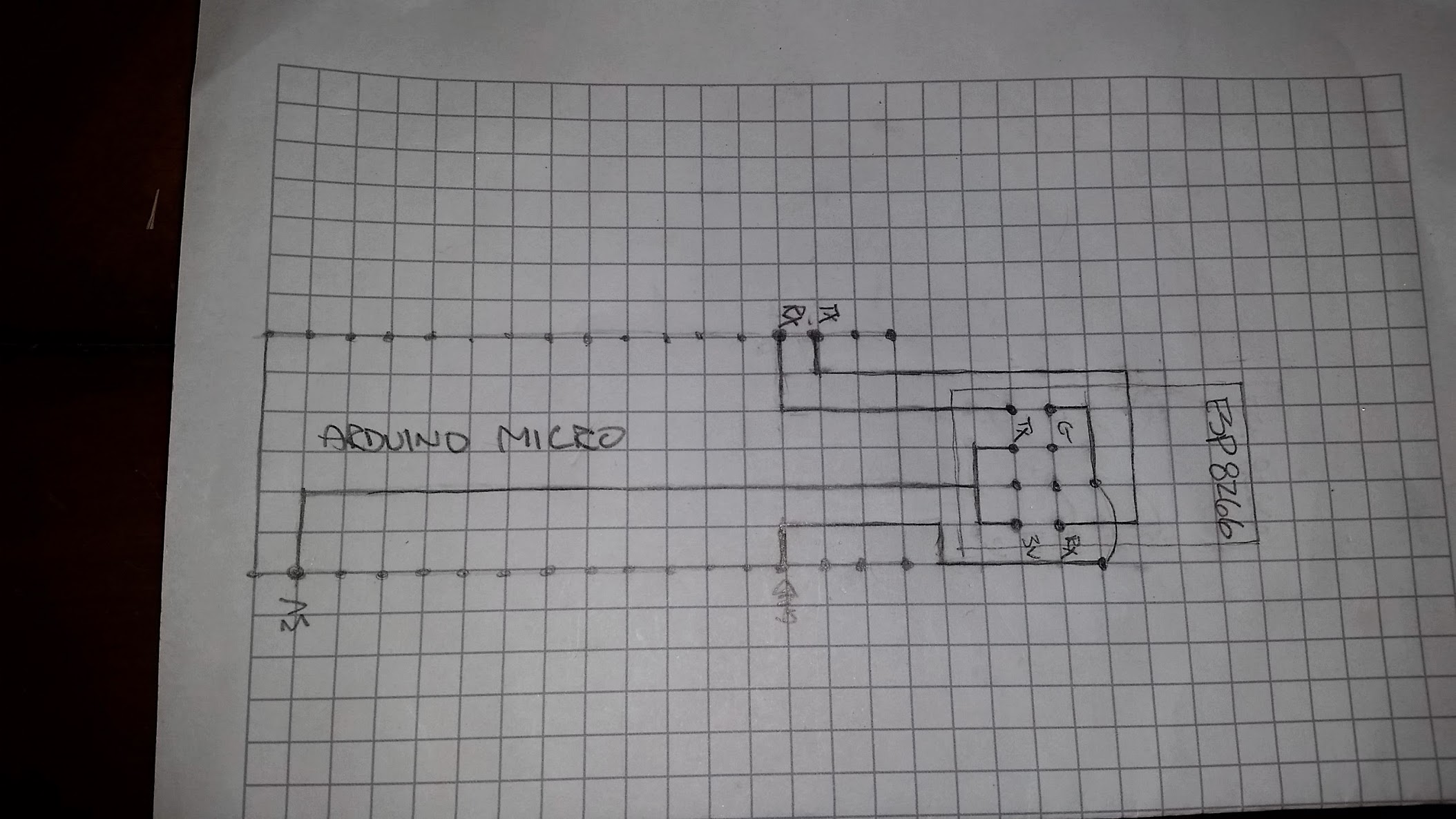
This design (on paper) shows the path from the TX, RX, 3V and GND or the Arduino Micro to the ESP8266. Normally I shoot for a one sided PCB, but in this case it turned out that was impossible. I had to have one small GND connecting black wire bridge, you can see it indicated on the lower right of the drawing
All the pieces including the headers for the complete board.
The design almost all together, with the holes marked.

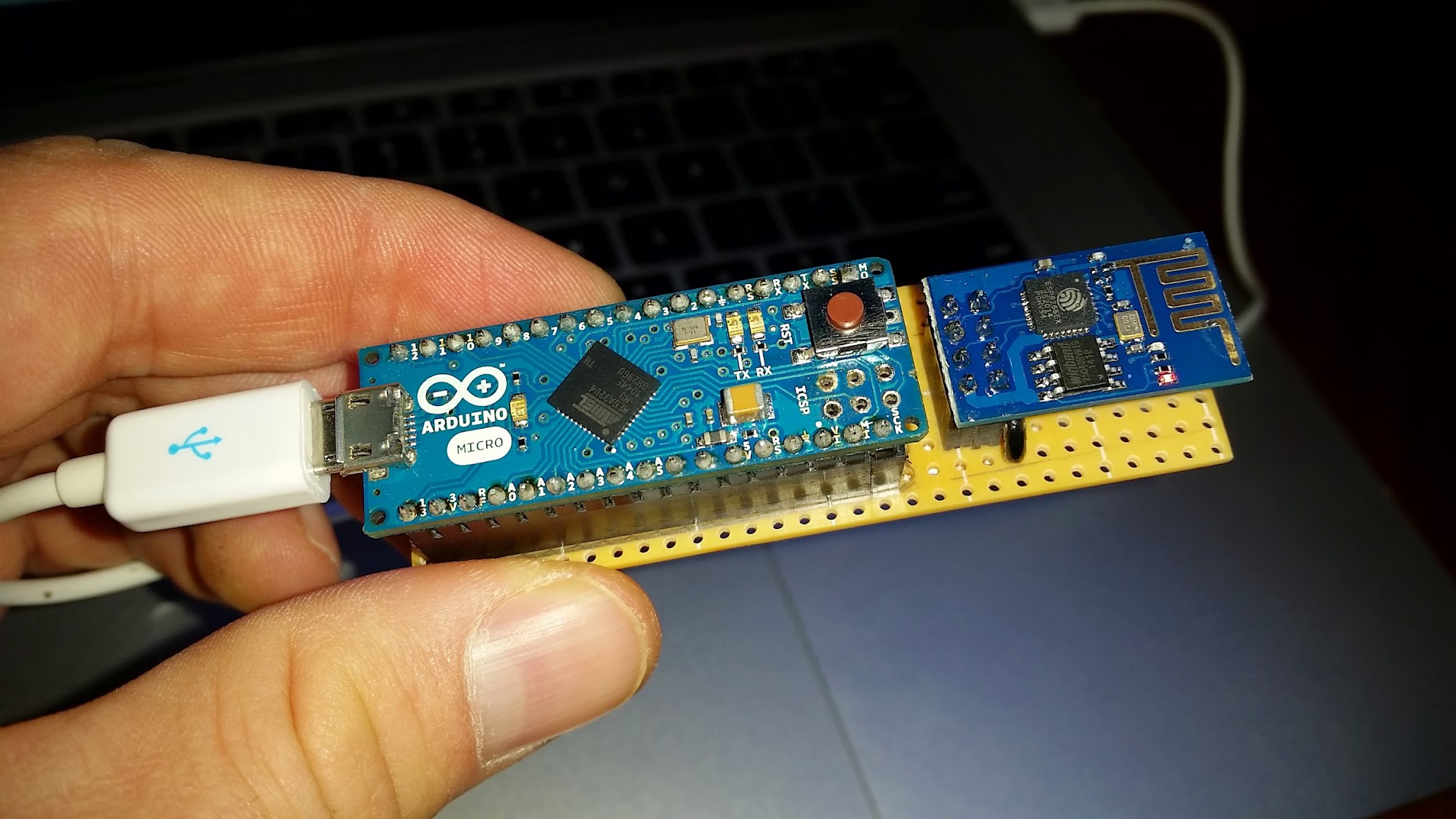
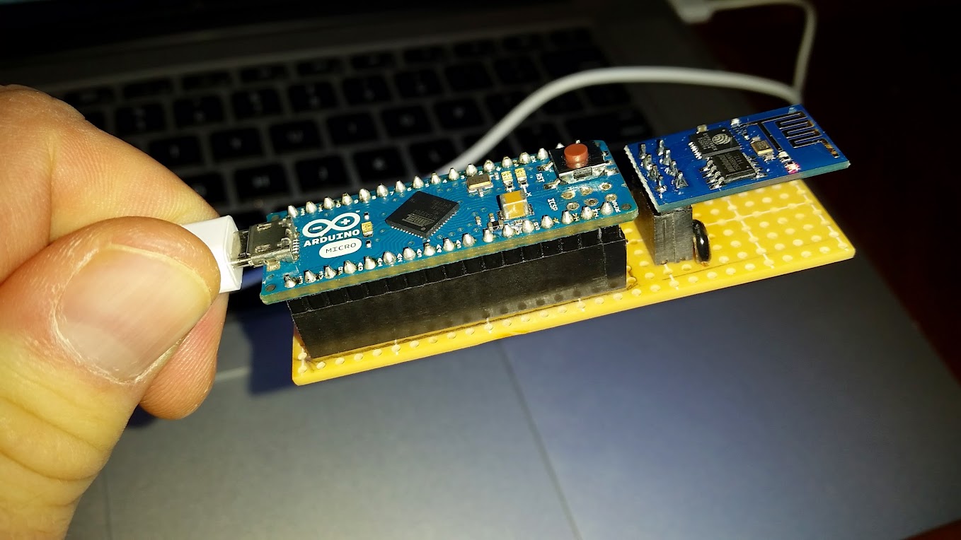
Finally complete, a cheap working version of an IOT (“Internet of Things”) device made with a $20 Arduino and a $5 Wifi board. Notice the ground connecting black wire on the lower right (as discussed above on the drawing).
Some very helpful links on using the ESP8266:
https://nurdspace.nl/ESP8266
http://www.electrodragon.com/w/Wi07c
http://www.instructables.com/id/Using-the-ESP8266-module/
UPDATES: After posting this, there were some questions on how I was able to run the the ESP8266 on the 3.3v line from the Arduino. Some suggested that this shouldn’t be possible because the Chinese spec sheets suggest that the ESP8266 requires 200mA to run. I attached a voltage meter to see how much current the Arduino Micro was actually pushing through. It seems that the Arduino specs suggest that the 3.3v line could only do 50mA, but the voltage meter showed between 10-80mA was actually passing through. So much for the specs. Video proof:


Pingback: ESP8266 with the Arduino Micro | ContractorWolf.com
Pingback: Add Wi-Fi to Arduino Boards for $3 with ESP8266 Wi-Fi Serial Module
Very nice job with this. Just used it on my Mega and works like a charm. These things are a little fussy. Finally after hours of searching I actually found something that works. Thanks.
Jeff, thanks for the great feedback. Any chance you can post a link to a picture of how you have it wired up to the Mega? I have had a few people mention using the Mega (not everyone has a Micro, there are a lot more Megas out there). I think it will help other people to have a good guide to wiring it to the Mega. Thanks!
Hey just wondering if you have any updates about using the 3.3v arduino power. How far away from the wifi router were you? Are you still using this solution? I just ordered 3 of these so trying to figure stuff out before they get here. This article is super helpful! Thankyou!
I have 2 of these running at my house, one monitoring the temp in our bedroom and one monitoring the temp in the babies room. Both are not very close to the router (a few rooms away) but work without fail (and post out to the web every 20 seconds). One of the thinks that really helped me was hooking up one ESP8266 to my Arduino Micro and use the Arduino as a serial pass-through so that I could test the AT commands and see their results until I could work out the most appropriate sequence of commands. I think that the ESP8266 is auto-reconnecting to a known network, because my code doesnt seem to be effected when the Wifi drops out, but I would suggest testing that. Make sure you are setting the AT+CWMODE and check that you are actually connected AT+CIFSR, both of those tripped me up for a bit.
nohow..
That a very nice presentation James wolf..
so your prototype can send a analog value in a web page.
that also can send rfid tag value through wifi .in a web page.
rc 522 can seance rfid card.its pin sda,sck,mosi,miso,irq,gnd,rst,3.3v.
Tested with arduino uno.IT can print value of a rfid card.(serial monitor)
I want to connect micro+esp82266+rc522+display+keybord.
when a rfid card holder touch a card. module can seance and send tag id post out to the web every time.
Your project RFiD Project
1> single input value through single 1> Multy input value multy pin
input pin
2> It send voltage regist value. 2> It send hexadecimal value
3> this project is Ready 3> this project is ……
plZ help me about this project…
Does the ESP8266 automatically reconnect to the AP if it is disconnected? If not, is there a way to detect if the ESP has lost connection then reconnect if it has?
Also, where did you get the headers from? I need to pick up some female headers
I think it auto reconnects because my Wifi has issues sometimes, but these things dont seem to be effected by it. The headers are available at Sparkfun.com or Adafuit.com
How did you manage the 3.3V vs 5V difference in logical “1”? I’ve seen many articles including extra hardware for this.
I am using 3v power but the serial lines are still technically 5v coming off the Arduino Micro. I decided to just try it and see what happened. What I would suggest however if you werent willing to chance the board is using a 2 resistor voltage divider.you can find a good discussion on how to make it here:
https://learn.sparkfun.com/tutorials/voltage-dividers
You only need to do this on the Arduino TX -> ESP8266 RX line. The Arduino RX can handle the 3v coming out of the ESP8266 TX without adding anything.
Great! I was going to use the same, just wanted a confirmation from someone who has used it. Thanks! Also, it might be an unusual question, but is two way communication possible? The Arduino can read data from and send data to a server, right?
Martinv279, yeah the ESP8266 good at HTTP stuff so everything it does is both a send and receive. Each request is technically sending data to the server and waiting for a response to come back in the same way a web browser does. The code I have above is a simple HTTP GET (where all the info you are passing is on the query string in the URL) but you could do an HTTP POST the same way and include the text you want to pass in the body of the request.
What microcontroller are you connecting to the ESP8266?
Arduino Mega 2560 R3 and Arduino Leonardo. I regulated the voltages, and converted the logical “1” to a flat 3.35V.
yeah? solid, you shouldnt have any issues then. I actually have an updated example that is used for my temperature sensor here:
http://signalvehicle.com/iot2/
I will see if I can get that up on GitHub this weekend so that you can see another example of how I am using the AT commands to run the ESP8266.
Hy there.
I was wondering: can this module be setup so that it only receives messages? I’m interested in cheap ways of implementing wireless communication between my computer (hosting an nginx probably) and an arduino device. upon receiving data, the arduino will command a motor or something like that.
Thank you very much if you have time to respond.
Yeah this should be possible. I think I was able to communicate with the ESP8266 using telnet after I connected it to my wifi and verified that it had an IP address. When I sent it messages via telnet those messages came across the serial lines on the device and could be processed by the Arduino. You might need to set the CWMODE first using the AT commands, but you will have to read up on that because I didnt get too far into it, just did some basic testing. Definitely possible though.
Hi Guys,
nice project – only its quite difficult to get that AT+CMD stable, right?
Past few days I tried those radino WiFi modules and so far I can say this is exactly what we need.
The modules combine the Arduiuno Micro with the ESP8266 and the ESP is runnin an very stable radio Stack. There is a library “IC-ESP” for Arduino that implements easy to use commands to
run TCP/HTTP servers, set up AP, set up as client, TCP push and so on.
here is a link to the library: http://wiki.in-circuit.de/index.php5?title=IC_ESP
I think the radino Module itself is also fair pricing of less than 20$
I connected temperture, humidity and lux-sensors and got it work within few hours 🙂
Hey,
really interesting! Did you hear about the “radino Wifi” ? This one combines yout project into one wonderful small product!
-> Arduino Micro + ESP8266EX combined =)
Check out http://www.radino.cc or http://goo.gl/kGzkth or Amazon
The “radino Spider” contains an 5V to 3.3V supply already. So nice All-In-One solution!
Keep up the good work!
regards
oh sorry, just noticed that Andy already mentioned this in the comment above :3
Good article, but I have a problem with the voltage from the Arduino mega TX. I use the power supply from the Arduino Mega (3.3 V), and a voltage devider that I have tested and it works fine. But when I connect everything the voltages on the ESP are all fine (3.3V) except the ESP RX, it recives 0.13V from the devider. But the Vin on the devider is TX from the arduino, and it is 0.13V also. The ESP has power, but I have no connection. Should i try an external power source?
Alen, You only need the voltage divider on the line running between the TX (arduino) -> RX (ESP8266), you dont need it going both directions. I would also suggest running without any voltage regulation to start as you can see that is what I am doing above. Mine work fine without it.
Hi there!
I’m trying to make the code work on an Arduino Nano V3 and I get the following error when compiling:
DigitalReadSerial.ino: In function ‘void setup()’:
DigitalReadSerial.ino:5:3: error: ‘Serial1’ was not declared in this scope
DigitalReadSerial.ino: In function ‘void loop()’:
DigitalReadSerial.ino:22:10: error: ‘Serial1’ was not declared in this scope
DigitalReadSerial.ino:38:8: error: ‘Serial1’ was not declared in this scope
DigitalReadSerial.ino: In function ‘void WebRequest(String)’:
DigitalReadSerial.ino:75:6: error: ‘Serial1’ was not declared in this scope
Yes, that is because there is no Serial1 on the Arduino Nano. Different boards have different capabilities. The reason I picked the Arduino Micro was its second onboard Serial so that I could use one for debugging and one to send commands to the ESP8266. You might be able to get it to work using software serial but there may be some issues with the baud speed because the software serial has limits on its baud rate and my ESP8266 needed to run at 115200.
Would it be an option to use a Micro to do all the setup and “debugging” work and once its working as expected move the project onto the Nano?
Bobbo,
That would certainly be an option. You could also use the SoftwareSerial for communicating with the ESP8266, which would still allow for normal serial debugging over USB on the Nano. When I first worked on this project I wanted the 2 separate Serial ports on the Micro so that I wouldnt be limited in the baud rate (like you are in SoftwareSerial) because I wasnt sure what rate the ESP8266 would need.
Pingback: Pentair EasyTouch interface « Coert Vonk
Hello,
I am trying this on arduino Uno. It is showing some error.
omowr
This report would have more information with
“Show verbose output during compilation”
enabled in File > Preferences.
Arduino: 1.0.6 (Windows 7), Board: “Arduino Uno”
esp.ino: In function ‘void setup()’:
esp:6: error: ‘Serial1’ was not declared in this scope
esp.ino: In function ‘void loop()’:
esp:24: error: ‘Serial1’ was not declared in this scope
esp:40: error: ‘Serial1’ was not declared in this scope
esp.ino: In function ‘void WebRequest(String)’:
esp:79: error: ‘Serial1’ was not declared in this scope
This is the erroe. Plz help me out.
Tomorrow I have my project submission. Help me Plz..
#include
SoftwareSerial Serial1(2,3);
include these lines on the first
Hi, I have been struggling with getting the esp8266 to work, my current issue is that I try to send a get request, it says “SEND OK” but the server gets nothing, not even in the access logs or the error logs. It also doesn’t print the server response. I have it wired to the main RX and TX pins of my UNO and I’m using the serial monitor to deliver AT commands directly to it.
Here’s an example of what happens during an AT session:
AT
OK
AT+RST
OK
`€ÉYbzþ€@Çr!Bú!KZôbÚ÷
[Vendor:www.ai-thinker.com Version:0.9.2.4]
ready
AT+CWMODE=3
no change
AT+CIPMUX=1
OK
AT+CWJAP=”iPhone”,”qqqqqqqq”
OK
AT+CIPSTART=4,”TCP”,”50.112.174.241″,80
OK
Linked
AT+CIPSEND=4,55
> GET /esp/?v=55555 HTTP/1.1\r\nHost: 50.112.174.241:80\r\n\r\n
SEND OK
OK
Unlink
Did anyone come across this? Are there any compatibility issues with iPhone’s personal hotspot?
I’m sure the format of the GET request is correct since it works over telnet. Also the page on the server should return HttpResponse “ok” and update the url “http://50.112.174.241/static/v.txt” with the value of v in “http://50.112.174.241/esp/?v=5555”. I’m using MUX=1 because otherwise I get a “link typ error”.
Please help me or direct me in the right direction and I’ll start researching.
Ibriham, try testing if you have an IP address after you connect to the Wifi network. Also, I think their is a requirement to send the RST command after setting the CWMODE (which I am setting to 1 where as you set to 3). I remember reading that somewhere in the documentation somewhere.
Thank you James! Things are still not working, I tried the following:
1- setting CWMODE to 1 before the reset command
2- checking if I have an IP, by the following command:
AT+CIFSR
172.20.10.8
OK
I still get a “SEND OK” but nothing gets sent.
Ibrahim (sorry I got your name wrong on the first try), Ok, some other weird behavior I found was that some servers (not all) wanted the full URL in the GET request. I would also eliminate the IPhone from the equation, try connecting to a normal wifi router.
Also, notice in my code I am doing not including the channel in my CIPSTART or CIPSEND, and on my GET request I do NOT have the Host or Port defined (like you are doing above). You need to make sure the CIPSEND has the length in Bytes of the GET request.
These lines are how I construct the CIPSTART and the GET request (from my code):
String startcommand = "AT+CIPSTART=\"TCP\",\"" + domain + "\", 80";

String sendcommand = "GET http://"+ domain + path + " HTTP/1.0\r\n\r\n\r\n";
You can try running my code from github, and modify it as needed:
https://github.com/contractorwolf/ESP8266
Read the readme file carefully as well for exact instructions on how to run it. It outputs all of the commands it is using to the Serial Monitor so you can see exactly what order they are being executed. Dont give up, you have the network connection, you just have to figure out the HTTP request and you will be able to pull in all sorts of data. I spent about 2 weeks to get my code running correctly, so I understand the frustration, but you are almost there.
I finally got it to work, I did the following:
1- set CIPMODE=1
2- replaced all the \r\n by actual newlines
3- added an extra newline after the header
I hope this helps someone someday 😀
Ibrahim, can you paste the full listing of your commands so that someone else can see the full solve?
AT
AT+CWMODE=1
AT+RST
AT+CWJAP=”iPhone”,”qqqqqqqq”
AT+CIPMODE=1
AT+CIPSTART=”TCP”,”50.112.174.241″,80
AT+CIPSEND
GET /esp/?v=th_time_to_send_a_request:D HTTP/1.1
Host: 50.112.174.241
{{Press Enter Again}}
I’ll post the function as soon as I get it written along with the firmware vresion
Ibrahim did you press enter after AT+CIPSEND ?
I have succeced by sending GET request using Hyperterminal, but when I used the same code request the module just replied “bussy….”. then I separated NL and Carriage return by 3s delay the transmition success, what the different by pressing “Enter” in Hyperterminal and use a code “.println” or “\r\n” in arduino?
Thank you Ibrahim..It really helped me..Did you check the FTP accessibility of ESP8266?
is it possible to access FTP with esp8266 12E module?
Hi Athul, did manage FTP access? I’m sweating through this now.
Hi Everyone.
I have a very simple question regarding ESP8266 wifi module. Can we use this module without arduino board, or any other other programming board. e.g, I want to use it with PIC microcontroller directly, (without arduino).
Abdul, yes you can use the ESP8266 with a PIC micro. The ESP8266 can be controlled by any micro that can do serial (UART) communication using AT commands. You just connect the TX/RX lines and send text commands over the serial port. If you send the command “AT” (without the quotes) to the board from the PIC to the ESP8266 you should receive an “OK” response from the ESP8266. The lines will need to be connected like this: PIC TX -> ESP8255 RX and PIC RX -> ESP8266 TX. You will also need to supply the 3.3v and GND for the ESP8266.
Hello, thank you for your information, it’s really a good job. but can you help me please because i cannot make it run, i have this issue :
message: AT+RST
COMMAND REQUEST
AT+RST
OK
ets Jan 8 2013,rst cause:4, boot mode:(3,7)
wdt reset
load 0x40100000, len 816, room 16
tail 0
chksum 0x8d
load 0x3ffe8000, len 788, room 8
tail 12
chksum 0xcf
ho 0 tail 12 room 4
load 0x3ffe8314, len 288, room 12
tail 4
chksum 0xcf
csum 0xcf
2nd boot version : 1.2
SPI Speed : 40MHz
SPI Mode : QIO
SPI Flash Size : 4Mbit
jump to run user1
rl�B�
Ai-Thinker Technology Co. Ltd.
invalid
any advise please ?
I think that actually may be a valid reset for the ESP8266. I have heard other people talking about a slightly weird response message depending on the version of the firmware running. What else makes you think that it isnt working? Just that last line? If so I wouldnt worry about it. It looks like the board is responding to your commands. Let me know if it fails on the following steps.
Hello James, thank you for your response. effectively, even i have an ‘invalid’ response it’s work. did you have made it working like a web server ? if so do you have any advise ? another time thank you for this sample it’s save me a lot of time.
Hi james i have your post about esp8266, but i m having a problem i m using it with arduino uno . When i snd AT+RST i gives invalid instesd of ready. I m hoping that you could help me with it.
Awais,
can you give me each step of your interaction with the board? What does it do when you just send it the “AT” command?
AT+CWMODE=1
OK
AT+RST
OK
ets Jan 8 2013,rst cause:4, boot mode:(3,7)
wdt reset
load 0x40100000, len 816, room 16
tail 0
chksum 0x8d
load 0x3ffe8000, len 788, room 8
tail 12
chksum 0xcf
ho 0 tail 12 room 4
load 0x3ffe8314, len 288, room 12
tail 4
chksum 0xcf
csum 0xcf
2nd boot version : 1.2
SPI Speed : 40MHz
SPI Mode : QIO
SPI Flash Size : 4Mbit
jump to run user1
rlÿ
Ai-Thinker Technology Co. Ltd.
invalid
AT+CWJAP=”AndroidAP”,”kfan2227″
OK
AT+CIFSR
+CIFSR:STAIP,”192.168.43.120″
+CIFSR:STAMAC,”18:fe:34:a2:35:6f”
OK
AT+CIPSTART=”TCP”,”192.168.43.120″,80
ERROR
CLOSED
but in this case
AT+CIPSTART=”TCP”,”WWW.GOOGLE.COM”,80
CONNECT
AT+CIPSTART=4,”TCP”,”192.168.43.120″,80
on another matter I Have the same issue with the ‘invalid’ on reset although the module works fine .. except for the same problem with tcp connections (which works only if I connect to a local ip or my public ip)
I have looked all over and found nothing on the matter …. i felt like I am the only on earth with this problem … if you found something please tell me!
AbdEl-Rahman, can you give me the full rundown of the commands and response you are getting here in the comments? It will help me see if there is anything weird that might be preventing you from getting it working. Also, try just my code and only change the SSID and password to whatever wifi you are using and let me know if that is working.
And in response to AT+CIPSTART i gives ip error
James
I am waiting for your reply can you help me with it.
Sorry am on vacation so I didnt see this until now. Is that ip address you are trying to connect to a webserver? Can you hit it with your browser?
Yep thats the ip and when browsed nothing loads
Yep thats the ip and when browsed nothing loads
Awais, can you paste your commands and the responses into the comments? maybe I will see what the issue is.
Hi James, great video! I am a little bit stuck and I could REALLY use some help. So my friend and I are trying to send data through a server to a database (ESP8266 + Arduino, Apache Server and Mysql Database). When we send data, it says “send ok” and after that it says connection timeout. On apache it says 408 error. A few times we got 200 4961 (this is what we want) but that only happens when we send GET /HTTP/1.1 and when we send to GET/index.php?img=pngPlugIn HTTP/1.1. We try to send GET /pm/add_message.php?pmu=RAL005-07001-FL02-0030-2L Host:192.168……. but we get 408 320. Any suggestions? Do you know what we might be doing wrong?
can you send the request and response in the code blocks in the comments here? Its tough to make out what your issue is without seeing the full communication. Also verify that you are connecting and responding correctly by using something like google.com as your url
Pingback: ESP8266 | Mickology
Hey James,
Thanks for the great post, your code is elegant and straightforward. Very helpful.
Just something to note: the Mega is a little less quirky to get working if only for one simple issue: since the Micro has the native USB 32u4 chip it it doesn’t restart when the Serial monitor is opened so if using a new esp-01 chip you’ll have to manually change the CWMODE and set the ssid and password by feeding AT commands. Hitting the reset button doesn’t always work and makes the micro hang. I hate the 32u4, haha.
I also had to externally power my esp-01. The power from the micro was enough to just barely get it running but it would brown out and restart over and over again. Solved immediately when I gave it enough current (and a big decoupling cap on the power rails).
Thanks again!
Adiel, Thanks for the feedback! Thats weird since I have found that it doenst run the setup() when you restart the Serial Monitor but it does run Setup() when you hit the reset button. Also the ESP-8266 will remember and reconnect to the last Wifi it was connected to automatically. I am not sure with the ESP-01, I have only worked with the ESP-8266.
I did another video testing the power consumption of the ESP-8266 and found it to be ~200mA which you can see here:
I wouldnt suggest powering it from one of the digital pins which can only output around ~40mA, I only power it from the main power rail 5v. I have one of these running for months posting the indoor temp at my house to a web service every 60 seconds without issue.
I was powering it off the 3v3 pin, not a digital pin. I’m using the same esp8266 you are, the “esp-01” is just the form factor we’re using since the same wifi chip comes in different forms (esp-01, 02, 03, etc.).
I thought the reset button hang was a little out of character too. To be honest, it’s probably just my Micro that’s a little old and has seen better days, haha. Good to know that you’ve been able to run it non-stop for so long though. The esp8266 is a nice little chip.
Hello,
I tried working on this. I am facing issues with the ERROR when I send the HTTP request. My AT commands are working fine.
My AT commands work. HTTP request is timed out every time. I even tried different Arduino versions. Could anyone please help me? Thanks in advance!
try using the AT commands to verify that you are connected before executing HTTP requests
Can i use it stand alone like arduino? I mean without connect to arduino board or any other board
yes, there has been much work done with the ESP8266 since I first posted this project. You can now use the Arduino IDE to program the ESP8266 alone
Hola amigos alguien podria ayudarme me sale invalid al conectar el wifi
El mensaje “Invalid” no significa necesariamente que usted no será capaz de conectarse. Fijate a ver si otras personas han recibido el mismo mensaje: “Invalid”. ¿Puedes compartir en un comentario, los comandos AT que está ejecutando? Asi puedo revisarlo y ver si hay algo incorrecto. Nota: Estoy usando el traductor de google porque yo no hablo español.
Nice Nair, glad you were able to figure it out, would live to see your setup if you could upload a pic.
Thanks a lot. I was in a blink of halting this serial method and hardwiring directly to esp which is hard as I know.. again thanks and this will be my first post like this to comment on success.. its been 3 days I was searching for this result. .n the problem I faced was trying to put post method and that too with some syntax error. Wish you all success once again thanks, amigo.
Nair, glad you were able to figure it out, can you upload a pic?
I have a problem friend, if i open my serial monitor,, output is can’t read in serial monitor just write square -square? what is the problem friend?
you probably have the serial monitor set to a different speed then the arduino, check it an adjust so that the serial monitor and the arduino serial line are running at the same speed
I have 5v pro micro and a 3v3 esp8266 will there be any problem in serial communication between them ?
I dont know 3v3 logic of esp8266 may not be compatible with 5v logic of pro micro .
* Edit
Assuming that i would power esp8266 separately and common the ground with arduino pro micro.
People have suggested not doing this (which I obviously ignored for this application) but I found no issues with doing it. This thing ran months without issues. I have since moved on to using the ESP8266’s directly in the Arduino IDE (without an attached Arduino) and they work great like that. I also love the Wemos D1 chips which are basically a ESP8266 with a USB connection and a 5v regulator. Super cheap from China or on Amazon: https://amzn.to/34gVulY