This original idea came from a post I saw from a fellow Arduino enthusiast +Mohammed Al Sahaf, in his post he linked to a blog talking about using the Arduino’s PWM ability to act as a clock. The basic idea was to use the regular beat of the PWM as a tick of a clock. The measurement of the frequency is pretty accurate because of the nature of it being digital. This is a link to that original article that describe doing it with an Arduino Nano or Arduino Mega (mine uses the UNO):
http://www.instructables.com/id/Make-an-accurate-Arduino-clock-using-only-one-wire/
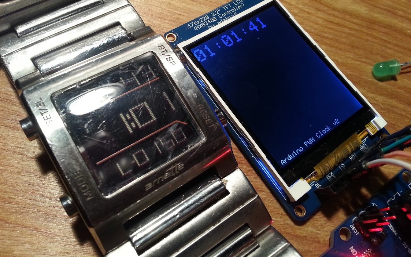
What I wanted to do was use my Arduino UNO with my Adafruit 2.2 TFT LCD:
http://www.adafruit.com/products/797
Adafruit Tutorial on how to use the TFT with the Uno:
http://learn.adafruit.com/2-2-tft-display
A PWM is basically a signal used by servos and it looks like this:
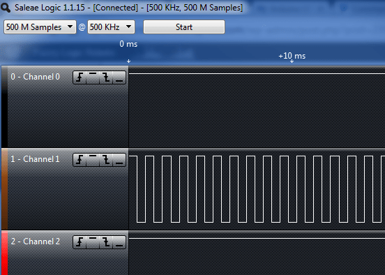
It is basically flipping a switch from 5+ to GND at a specific frequency. The servos are watching the frequency and moving accordingly. For the pin 6 PWM it appeared when testing the frequency using my Saleae Logic that the pin 6 was doing 974 Hz which means 974 on and off flips every second.
The important part that the original article suggested was using the interrupt as your timing mechanism because the interrupt takes priority over other code execution. This means that I could count on updating something like a screen, without that updating process interfering with the incrementing a second at the right time. If you try and use millis() in a normal Arduino loop you will notice that it quickly becomes less than accurate.
To get around the reliability of using millis() the article (posted above) suggests to use an interrupt. An interrupt is listening for a certain condition to happen on a digital pin. when the condition happens the function is called(and executed with priority). Interrupts are cool because they can insure that things ALWAYS happen in your code, and you don’t miss something important (example: a second being counted) because you code is busy elsewhere (example: updating a screen, long process). Here are the Arduino instructions on setting up an interrupt: Using Interrupts
The idea was that you could run a normal Arduino loop that updates the screen, and a PWM pin (pin 6 on the UNO) that you knew the rate of (974 Hz) and a pin (interrupt 0, aka digital pin 2 on the UNO) that you were listening for the ticks of the clock you could maintain a pretty accurate Arduino Clock.
At the bottom of this post is the code I am currently using on it. It is mainly from the Adafuit example code of how to use the TFT LCD but with all the image and line design code removed (just the text writing sections remains). I also have it outputting the time to the serial port at 9600 so that you can monitor it without the screen. (if you don’t have a screen you can remove all the code relating to the screen and it will work over serial just as well).
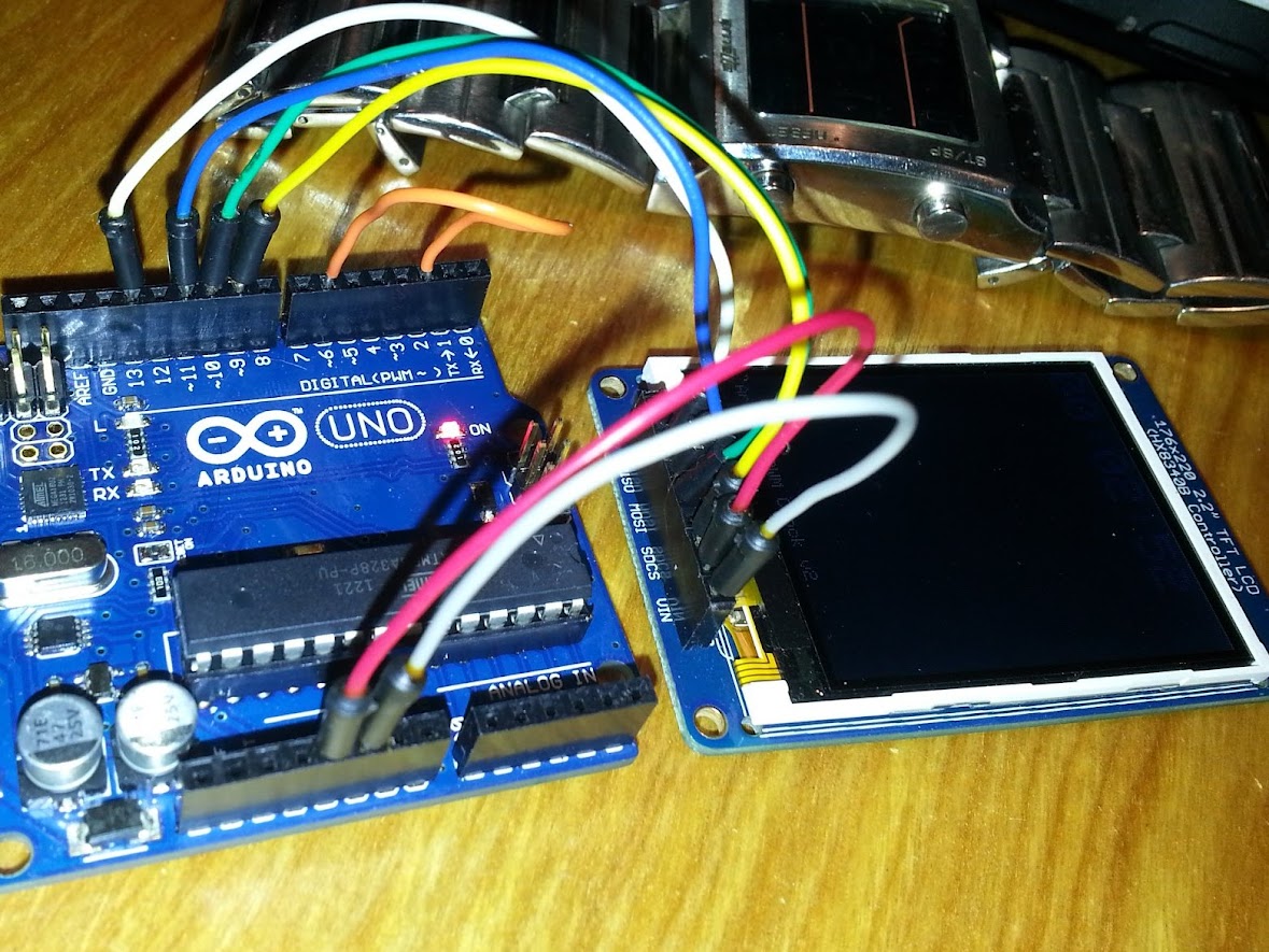
If you have the TFT this is how I have it wired up:
This is a video explanation with it working:
NECESARRY TO RUN THE CODE BELOW:
1. wire up the display:
http://learn.adafruit.com/2-2-tft-display/connecting-the-display
2. download and install the adafuit libraries in you arduino/libraries folder:
http://learn.adafruit.com/2-2-tft-display/test-the-display
//************START CODE COPY HERE

/***************************************************

  This is an example sketch for the Adafruit 2.2" SPI display.

  This library works with the Adafruit 2.2" TFT Breakout w/SD card

  ----> http://www.adafruit.com/products/797
Check out the links above for our tutorials and wiring diagrams
These displays use SPI to communicate, 3 or 4 pins are required to
interface (RST is optional)
Adafruit invests time and resources providing this open source code,
please support Adafruit and open-source hardware by purchasing
products from Adafruit!
Written by Limor Fried/Ladyada for Adafruit Industries.
MIT license, all text above must be included in any redistribution
****************************************************/
#include <Adafruit_GFX.h>
#include <Adafruit_HX8340B.h>
// if we're using fast hardware SPI on an '328 or '168 arduino such
// as an Uno, Duemilanove, Diecimila, etc then the MOSI and CLK
// pins are 'fixed' in hardware. If you'rere using 'bitbang' (slower)
// interfacing, you can change any of these pins as deired.
#define TFT_MOSI 11 // SDI
#define TFT_CLK 13 // SCL
#define TFT_CS 10 // CS
#define TFT_RESET 9 // RESET
// Color definitions
#define BLACK 0x0000
#define BLUE 0x001F
#define RED 0xF800
#define GREEN 0x07E0
#define CYAN 0x07FF
#define MAGENTA 0xF81F
#define YELLOW 0xFFE0
#define WHITE 0xFFFF
#include
// Option 1: use any pins but much slower
//Adafruit_HX8340B display(TFT_MOSI, TFT_CLK, TFT_RESET, TFT_CS);
// Option 2: must use the hardware SPI pins
// (for UNO thats sclk = 13 and sid = 11) and pin 10 must be
// an output. This is much faster - also required if you want
// to use the microSD card (see the image drawing example)
Adafruit_HX8340B display(TFT_RESET, TFT_CS);
//display
String appVersion = "Arduino PWM Clock v2";//"Arduino PWM Interrupt Clock"
int clockTextSize = 3;
int cyclesPerSecond = 974;
//pins
int clockInterrupt = 0; //interrupt 0 is pin 2 on UNO
int pwmOut = 6; //pin 6
//timekeeping
int seconds = 0;
int minutes = 0;
int hours = 0;
int masterClock = 0;//number of square waves
void setup(void) {
// clockInterrupt is our interrupt, clockCounter() function is called when invoked on a RISING clock edge
attachInterrupt(clockInterrupt, clockCounter, RISING);
//I always give enough time to restart if its locked
delay(2000);
//start serial communication for debugging
Serial.begin(9600);
analogReference(DEFAULT);//not sure if this is needed
display.begin();//starts the screen
display.fillScreen(BLACK);//wipe screen blank
display.setCursor(5,210);//bottom line of screen
display.print(appVersion);
Serial.print("writing to pin: ");
Serial.println(pwmOut);
analogWrite(pwmOut, 127); // this starts our PWM 'clock' with a 50% duty cycle//digital pin 10 for analogWrite pwm out
}
void loop() {
tftPrintTime();
serialPrintTime();
delay(800);
}
void clockCounter() // called by interrupt 0 (pin 2 on the UNO) receiving a rising clock edge PWM
{
masterClock ++; // with each clock rise add 1 to masterclock count
if(masterClock == cyclesPerSecond) // 974hz on pin 6, may be 490Hz if you use pin 9 or 10
{
seconds ++; // after one cycle add 1 second
masterClock = 0; //reset clock counter
if(seconds==60){
minutes++;
seconds = 0;//reset seconds counter
if(minutes==60){
hours++;
minutes = 0;
}
}
}
return;
}
void tftPrintTime() {
//display.fillScreen(BLACK);
display.fillRect(0, 0 , 170, 45, BLACK);
display.setCursor(0, 5);
display.setTextColor(BLUE);
display.setTextSize(clockTextSize);
if(hours<10){
display.print("0");
}
display.print(hours);
display.print(":");
if(minutes<10){
display.print("0");
}
display.print(minutes);
display.print(":");
if(seconds<10){
display.print("0");
}
display.println(seconds);
}
void serialPrintTime(){
if(hours<10){
Serial.print("0");
}
Serial.print(hours);
Serial.print(":");
if(minutes<10){
Serial.print("0");
}
Serial.print(minutes);
Serial.print(":");
if(seconds<10){
Serial.print("0");
}
Serial.println(seconds);
}
//************END CODE COPY HERE

Pingback: Arduino PWM Interrupt Clock | Fuzzy Logic Robots
how we know about the frequency required for pwm?
in the your source at “instructable” it is said using frequency 980 (counting 0 to 979) for high speed. While you here says it is 974. Which one the correct? Can you give brief explanation how the number comes?
Thanks.
Adi, I was looking at the output from my Saleae Logic and it showed that the PWM was operating at 974hz (look under the screenshot of the Saleae Logic). What I actually found was that this number itself was effected (slightly) by the ambient temperature and to have a really accurate timekeeper you would have to offset your numbers by recalculating based on temperature. Hope that helps, I actually didn’t go much farther with this than what you see on this page.
delay esta consumindo 1 seg a cada 5 seg
delay is consuming 1 sec every 5 sec
I am not sure what you mean there. The delay is just between screen updates and doesnt effect the pwm controlling the interrupt.
Appreciate you bllogging this