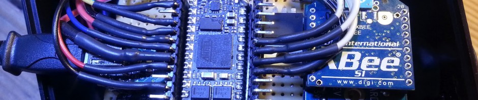
My plan here is to use the $9 Arduino Nano and the Roving Networks RN-171 serial wifi to make a wifi enabled sensor that can post to the cloud. First step i had to do was solder some legs on the smd wifi chip. These pads are small but you can see in the pictures that i have 4 legs now: tx, rx, gnd and 3.3v.


I put this new setup on a breadboard so that i could reconfigure the pins as needed. I like this sort of “dead-bug” construction.

Next up I have to communicate over serial with the part and has a lot of questions about the best way to do it. For now I am toing to use my FTDI Basic USB from sparkfun.com and teraterm at 9600 (from the user guide). Ill let you know how it goes.

Any update on the RN-171 project? Did you power it up? I bought one but haven’t had time to solder on legs and put it on the breadboard. From what I read, you can do all the programming/config through telnet. Then it’s just attaching some sensors to the analog IO and reading the input…
Rafie, have made pretty good progress, here is where I am at: I have wired 4 main leads to the 3v, GND, tx and rx. I can send the device commands over serial and watch the data come back. So far all I can do is “scan” and a few other commands that return data. I have not yet been able to get it to connect because I am struggling to understand how to make a real antenna for this. I have tried a couple of different ideas but they all still return 0 results. Pin 24 is the antenna pin and I have tried just attaching it to a long wire (no luck), coiling a wire (nothing seen) and even attaching it directly to the antenna that comes with my RN-XV but I cant get it to find anything on a scan. It definitely works, serial communication allows me to see and configure the device as needed, but right now I am stuck on how to make a DIY antenna for this device, any guesses?
Well, it has been a while since I read up on the module… I remember a few points I came across:
1) Make sure the module isn’t in any mode that would interfere with what you want it to do (ad-hoc, vs. infrastructure, no transmit, SPI mode, etc).
2) Make sure the pins are not floating (which could cause a mode to trigger). Look at the data sheet and see which pins should definitely be grounded or set to high.
3) This last point is a sad one: damaged transmitter by running it without an antenna. I read this only once, somewhere (can’t remember for now, it was some forum, I’ll try to find it), but I really hope that’s not the case.
I would read over the datasheet provided on the Roving Networks site and check the pinout. While you may only need vcc, gnd, tx & rx, other pins should be soldered and set/grounded.
I’m planning to use it standalone, without a microcontroller, just to read sensor data and maybe connect a transistor/relay to turn on/off something. Still not sure if that’s possible…
Rafie, as it turns out although that board has a pad for the U.FL connector is is not attached. I talked to an engineer from Roving Networks after soldering on the U.FL connector and it having no effect on the ability to see anything. I have decided (albeit reluctantly) to scrap the idea of using the RN-171 and instead use the RN-XV as my Wifi module on this idea. It has a pre-wired U.FL connector and seems to work well (tested with the FEZ Panda). I will post more info when I have the RN-XV wired to the Nano. I may even do my first etching to make a special board that will allow me to have them connected in a way that is easy to separate if needed. Ill let you know how it goes.
Unfortunately for this one it seems that using the pin 24 with a wire antenna would not work, you had to use their specs for a PCB of an exact thickness in order to correctly attach the antenna. Even the U.FL pad is disabled in the software (from the roving networks tech I had on the phone, who was very helpful). So a nice board but the antenna options on it are not DIY friendly.
I recently got the RN-171 working using the same type of connection methods you are using, I took a piece of wire about 2″ long (i believe it is 24 gauge solid core), wrapped it around a pencil to form the wire into a spiral (removed the pencil) and then soldered the wire directly to the antenna pin. It currently is able to see my home network and communicates well.
did you leave one end of the wire open and solder the other or did you form a loop and solder both ends to the pin 24? can you post a link to a pic? it might help other people too. thanks!
Hello, i’d really like to know how you did it too!! I’m in possess of an rn171 and i’m not being able to make it work. Some photos would be appreciated a lot. Thanks in advance.
Sketch Arduino WiFi for Wifly modem configuration without library and
with front-end: https://dl.dropboxusercontent.com/u/101922388/WiflySanUSB.zip