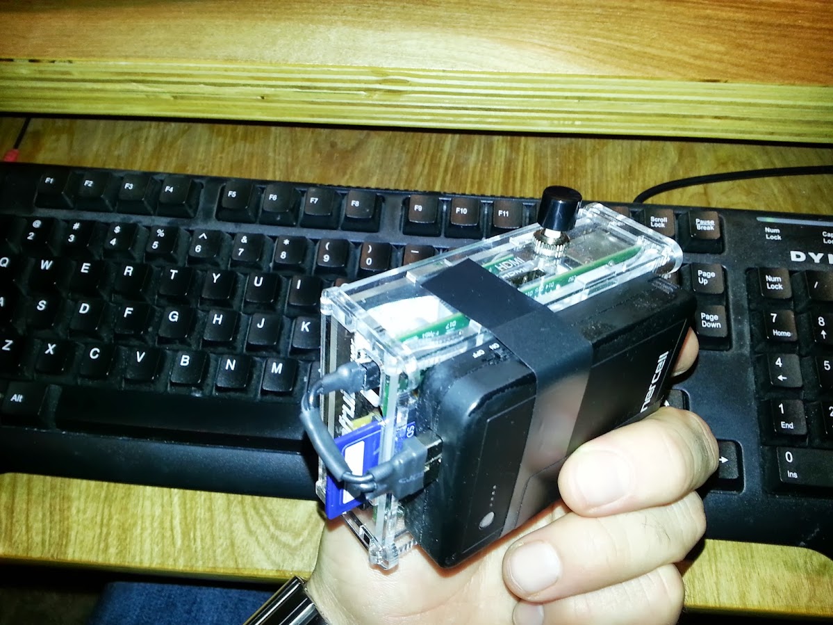
For my second real project for the Raspberry Pi I needed it to be something that took advantage of the recently released Raspberry Pi Camera Board. My idea was to make an extremely simple “point and shoot” camera. I wanted it to be able to run on batteries, connect over Wifi and have as much of the project inside of the original box as I could.
The connection to the button is done with a little proto-board from Radioshack (I like the ones with the square pads). It is basically using the schematic form this Adafruit tutorial on using buttons with the RPi. It just has a pullup resistor and a GPIO pin for each button you need. I just cut the RPi ribbon from Adafruit to make the attachment to the Raspberry Pi. I only have one button wired in, but you could do more or have LED indicator lights using the GPIO pins.
I will do more detailed instructions this weekend but to run this you will need to do the minimum:
Install Raspbian
http://www.raspberrypi.org/downloads
Install Camera with raspi-config
http://elinux.org/RPi_raspi-config
Update Upgrade your Raspberry Pi
http://www.youtube.com/watch?v=Vwrxep7oB24
Install GPIO
http://learn.adafruit.com/adafruits-raspberry-pi-lesson-4-gpio-setup/configuring-gpio
Install FTP (for external access to images, not required)
http://www.instantsupportsite.com/self-help/raspberry-pi/raspberry-install-ftp/
Run Camera.py
The Python file that is just loops waiting looking for a button press, the simple file is here (as a google drive file for save viewing):
https://docs.google.com/document/d/1Vw2p3fOsnDuoKzQon0poB2j5vHaJv4W7qtv2h11C9GQ/edit?usp=sharing
(the simple camera version, with no display)
I also made an updated version that uses a TFT screen and displays each picture after it is taken. The Updated version is available on GitHub here:
https://github.com/contractorwolf/Camera
(requires that PyGame is installed on the RPi)
It needs to be running in order for the camera to fire, so you may need to have your Pi boot right into it.
The final piece was making the ultra tiny USB cable using a slice from normal sized cable and some careful soldering and glue gun usage. This way it locks in nicely and the Enercell battery lasts about 3.5 hours.
Parts needed for this Project:
Raspberry Pi – $35
http://www.newark.com/raspberry-pi/raspbrry-modb-512m/model-b-assembled-board-only/dp/43W5302
Raspberry Pi – Camera Board – $25
http://www.newark.com/raspberry-pi/rpi-camera-board/add-on-brd-camera-module-raspberry/dp/69W0689
Case for the RPi – ~$10
http://www.phenoptix.com/collections/raspberry-pi/products/adafruit-pi-box-enclosure-for-raspberry-pi-computers
Ribbon Cable – $3
http://www.adafruit.com/products/862
Button Board and button from Radioshack -$10
http://www.radioshack.com/product/index.jsp?productId=2102843
http://www.radioshack.com/product/index.jsp?productId=2062496
Not required but extremely helpful when learning the Raspberry Pi:
Getting started with the Raspberry Pi – by Matt Richardson ($12)

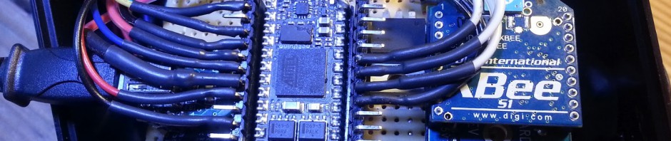
Button Shield using GPIO and Ribbon Cable
 |
 |
This is a ribbon cable that was cut and systematically wired into the proto-board. I wired in all the pins even though in this case I am only using a few. This was because in the future I may want to add additional buttons or use other pins and this sort of setup means that the project can grow without having to start from scratch.
NOTE: You can see that I actually have 2 pull-up resistors wired to pins 23 and 24, but I am only using GPIO pin 24 right now but pin 23 is ready for an additional button as is. I was thinking of adding the second button for taking a video but have not yet had a chance to work that out.
The way that the pins need to be wired to the Raspberry Pi is like this:

(from the Adafruit example on wiring buttons to the RPi here)
Then you can test to see if they are pressed in python like this:
if(GPIO.input(24)==False):
This line of code looks to see if the GPIO pin 24 is currently grounded (i.e. pressed), The pull-up resistor prevents this pin from appearing grounded unless the button has been pressed.
Mini USB cable
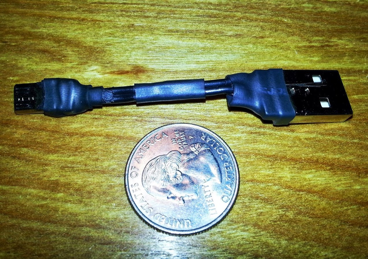
The USB cable can be easily made by cutting and shortenting any USB micro cable or done by purchasing these components from adafruit:
http://www.adafruit.com/products/1390
and
http://www.adafruit.com/products/1387
but if you buy these make sure that the wire you are using is thick enough to carry the current needed to power the RPi (my first attempt failed because I was using very small ribbon cable).
Autostart the camera.py file
Another thing I needed in case I had to switch batteries without connecting back to a screen was to make sure that it started the application on every boot. To do that I added a single line of code to the LXDE autostart file. I chose this file instead of a few other options because I wanted it to boot into LXDE and run the application in a terminal window from there so that I could see the button presses on the desktop. The file I edited is here:
/etc/xdg/lxsession/LXDE/autostart
and the additional command I placed at the end of the autostart file was this:
@lxterminal -e “sudo python /home/pi/camera/camera.py”
This basically starts an LXTerminal window and asks it to execute the command that starts the camera.py application
More Pics of the Camera
 |
 |
 |
 |
If you want to see the kinds of photos that can be taken on the RPI I put and album up showing a set of pictures I captured after making the first version of the Camera. That Album is here (ignore the first pic, that was the older prototype):
https://plus.google.com/u/0/photos/100923804654788847953/albums/5885619674563174641
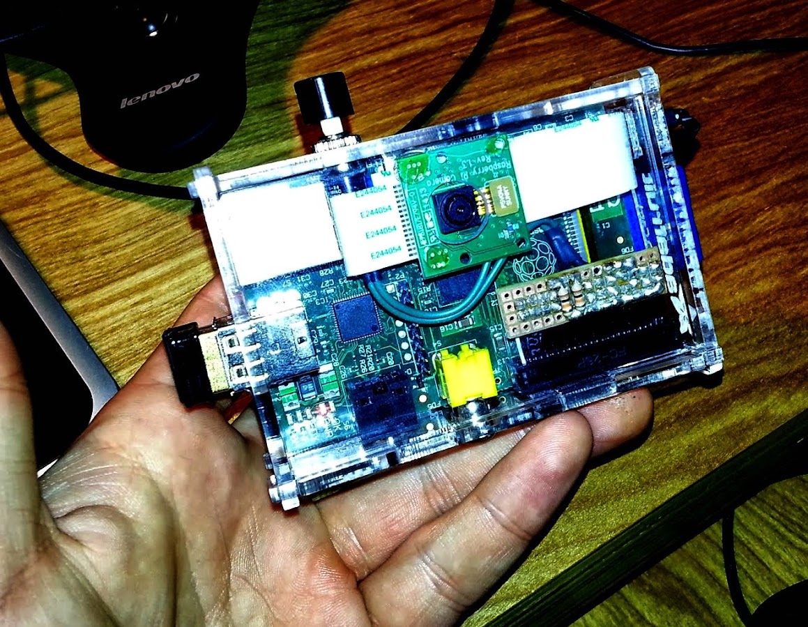
Next Steps: The Screen
 |
 |
Right now I am working on getting the screen (image above) working using just the 5v power from the Raspberry Pi GPIO header. To do this I plan on using a buck booster to convert the 5v to a 9v to keep in the 6-15v required by the screen. I may see if I can lower the voltage to 6v or see what the minimum the screen will work at in order to keep power waste to a minimum.

Awesome keep up the ROCKSTAR work!
Pingback: Community Corner: Projects Shared By Adafruit Industries - Limor Fried and Dozens More « adafruit industries blog
Pingback: Raspberry Pi Point & Shoot Camera #piday #raspberrypi @Raspberry_Pi « adafruit industries blog
Awesome stuff. Great project. Going to re-blog it.
Pingback: Point & Shoot Camera with the #RaspberryPi | Raspberry PiPod
Pingback: Community Corner: Pre-Programmed Arduino Light Show and More from This Week in Adafruit’s Community « adafruit industries blog
Hi, Very nice job. thanks for sharing this. I have a question, why is the camera taking a picture every second (without any GPIO connected), but if i press the button the camera stops taking pictures. I mention that i have model B rev 1 board with latest raspbian. many thanks in advance, Georgian.
Georgian, sounds like you have the GPIO pins not wired correctly, can you post a link to a pic of how you have it connected? the button press should ground the pin, and it needs a pull-up resistor to power. Take another look at my diagram and send me a pic to look at. Sounds like the GPIO is wired in reverse because pressing the button does the opposite of what you need it to do.
http://postimg.org/image/7n13a3knb/
http://postimg.org/image/p1ptkwcyx/
Thanks for answer, I took the best quality pics i could. Look like all the wires are correctly. I have to mention that some time ago I done something similar ( internet radio with 20*4 LCD) and it acted the same, I solved the problem by changing “if(GPIO.input(24)==True):” with “if(GPIO.input(24)==False):” and worked fine after. But in this code it is already “False”. I’m not using any program that is using the GPIO port, so i don’t think it they are already used by other program. Thanks for help and sorry for my bad english.
Use a voltmeter to check your circuit. It looks right from here but maybe the button is reversed (i.e. a button that opens when pressed as apposed to closes?). Make sure that your green wire is delivering the proper voltage and that even through the resistor has some (albeit small) voltage. Make a program that just outputs the value of the pin 24 and play around with it (attach is straight to ground), but DO NOT ATTACH PIN 24 STRAIGHT TO THE 5v pin, only through the resistor (its not able to handle 5v input). Also make sure you look at the pinouts for the version of the RPi that you have, there are some small differences in the versions as I have seen, mine is one of the older RPi’s so keep that in mind. Let me know what you find out. Post the version of the RPi and a link to the Pinout diagram you are using.
Hi, first i want to thanks you for all your support. Thanks!
I solved the problem by replacing the push button (for some reason sometimes was stuck to close position, weird. I throw it in rubbish straight away). now i got a decent push button and soldered wires to it. inside the shrink tube is the resistor and the other two wires and also the GND. Now i can’t wait to get box for it and make a self shoot in the mirror :)).
Many thanks again for this great project. Georgian
http://postimg.org/image/lyl04xd9v/
Georgian,
EXCELLENT! I thought it might have been something weird like that. Glad to hear you were able to properly test it and figure out where the problem was (and remove it). Looks good, smart idea placing the button hidden away in the shrink tube. I posted a new video (top of this page) that shows mine with the Adafruit display screen. Also if you use google+ I am here:
https://plus.google.com/u/0/100923804654788847953/posts
I post regularly about my projects and other fun electronics.
Glad my project helped.
James
Pingback: Make a Point and Shoot Camera with a Raspberry Pi | qazwilson
Pingback: Make a Point and Shoot Camera with a Raspberry Pi | Binary Reveux
Pingback: Make A Point-And-Shoot Camera With A Raspberry Pi | Lifehacker Australia
Nice done man. I will bookmark your blog!
Fantastic project – I’ve been looking for a way of taking pictures with a GPIO input for my Holga Pi – Raspberry Pi fitted into a medium format camera – project – details here: http://kimondo.co.uk/holga-120-d/ I have found a supply of really slim usb cables which helps a lot with fitting things into the case.
Nice Holga Pi project! You know it wasn’t too hard to get the screen working with the Raspberry Pi (through the vga). Adafruit has it in a few different sizes. You could install it in your project pretty easily. I took a working USB cable and cut just the ends into a super short USB cable.
Pingback: Aparat foto cu Raspberry PI | Robofun Blog
Do you think that this display:
http://www.raspberrypirobot.com/1-8-tft-lcd-display-raspberry-pi-expansion-board/
Would work for a project like this?
I’m pretty good with Linux, very good with soldering and circuits, not that great at proramming… I’m about to receive a Raspberry Pi with the camera in a few days and am very excited at the idea of building a digital camera. Just wanted to know what you opinion of a display like this, not exactly mainstream from what I can gather. Anyway, thanks!
-John
Now all you have to do is add a GPS to embed the location data in the photo file! excellent work!
thanks m005kennnedy!
Pingback: Make a $126 digital camera with touchscreen using Raspberry Pi | Digital Trends
Pingback: DIY一个带WIFI的树莓派照相机 | Boyd Wang
Wow that’s AWESOME!! I’m really impressed with the quality of the photos too, having had a flick through your album on G+.
I’ve only just received my Pi (a Christmas present from my wonderful GF <3) and after discovering the camera add-on(s) and the various TFT add-ons the first though I had was a custom "point-n-shoot" camera combined inside a typical hand-held sized case so I'm REALLY impressed with your work.
I look forward to seeing your progress with the TFT screen addition and perhaps braving a go myself one of these fine days! 😀
Thanks
very nice and awesome project . i have been looking for this project and i got from your website.. thank you pal, but i have a doubt when i run the code in python it show an error as UNEXPECTED INDENT near (DEF TAKEPIC) , can you just help me out wit that and sorry for my bad english.
thank you
Ahmed, no worries, that is probably because Python pays special attention to indenting. You may have made an error in how you copied and pasted the code in. Make sure you double check all the indenting in the code you are using. If you have some indenting that doesn’t make sense to the compiler, it will give you that error. Just read through your code, I am sure you will be able to find it.
ya i cross checked the code more than 3 times and then i posted was unable to resolve it so.i have installed python and also gpio too but don’t know why it is showing that..
Ahmed, that is a compile time error. If it is saying that there must be something off from your indentations, start by pulling the later parts of the code out and seeing if you can get it to stop saying that, then add them back in one block at a time (a “block” is identified by code that is run sequentially and is indicated by being indented together).
Also, maybe copy and paste the code into a new file so that the Google Doc formatting doesn’t mess up the indenting.
hi awesome project loved it and am trying it too.actually am new to this RAspberry Pi so having a doubt how can i get back to desktop if i want after that camera screen comes when power is on..
bhoobalan, ok good question. Like most python scripts a hitting “Control-C” will kill it and take you right back to the OS.
Am sorry, am not getting it out. i pressed that ‘control c’ even after that also not coming.. is there any other option.
thank you
bhoobalan, I think I forgot that I needed to put a check for that, try to add this in the first part of the while loop like this:
while(True):
for event in pygame.event.get():

    if event.type == pygame.QUIT: sys.exit()
I updated it in the code, thanks for pointing it out. Let me know if this solves it for you.
(with appropriate tabbing)
well thank you . this has hepled me alot with my project.. i just request you just keep on updating this type thank you
Pingback: Crea tu propia camara a base de un Raspberry Pi | LiGNUx
Pingback: DIY WiFi Raspberry Pi Touchscreen Camera | Developer's blog
Pingback: Podcast 123 – My posture picture | 64
Pingback: DIY一个带WIFI的树莓派照相机 - 极客范 - GeekFan.net
Pingback: Point & Shoot Camera Built With Raspberry Pi - DIY Photography
hi sir i got error in below
pygame.error: video system not initialized
pls help me
thanks
sk
Suryakant, can you send me the full error? are you using my code exactly?
hi sir got below error
pi@raspberrypi ~ $ sudo python camera.py
Raspberry Pi Camera with Buttons
Traceback (most recent call last):
File “camera.py”, line 94, in
for event in pygame.event.get():
pygame.error: video system not initialized
pls help me
thanks
sk
Suryakant, check you code for me, does line 94 look EXACTLY like this:
for event in pygame.event.get():
if event.type == pygame.QUIT: sys.exit()
make sure it says pygame.QUIT and NOT pygame.quit()
(I had that issue in my original posted code and saw that described when I googled your error)
also, which version of Python are you running?
This sure is a great project! I think I’ll be able to take some info from your work while working on my wearable Raspberry Pi project. I just think one wouldn’t need any desktop environment – I think that for the screen you can just use framebuffer (http://en.wikipedia.org/wiki/Linux_framebuffer). There must be a tutorial for working with framebuffer from Python somewhere out there, and I guess I’ll make one as I’ll work on it.
CRImier, that is interesting about the framebuffer. I hadnt thought of that. Let me know if that works out for you.
Pingback: Lista della spesa – Pi Camera – TGLabs
Mind if I ask what the build time for this project was?
The total build time if you had all the parts together and the SD card already with Debian installed is around 3-4 hours, depending on your ability to solder and install libraries on Linux. Everything you need is here in the instructions, let me know if you have any questions about the steps.
Pingback: 3 Raspberry Pi Camera Projects | Initial StateInitial State |
Pingback: Vijf DIY projecten voor je Raspberry Pi camera - Mancave
So cool! I read similar articles on http://ngin.pro/index.php?do=cat&category=raspberry_pi
That’s really great! But I have a 3.5″ pitft+ on my Raspberry Pi. Do you know what modifications I need to make to the code in order to get this script to work? I already started from scratch after I installed and failed!
Ed, should work fine with the pitft without any changes. Adafruit did a nice updated version a few months after I did this one that also used a pitft screen. They were nice enough to include my video on their detailed instructions:
https://learn.adafruit.com/diy-wifi-raspberry-pi-touch-cam/overview
That should get you what you needed to get the screen running, did you get the OS installed ok? what about the camera module?
Hi, i have a problem with the camera, i hope you can support me.
I run the script, but the screen turns black and i cant see anything, the camera module have a led for the on-off, and its on.
I have changed the module, and its the same result.
Do you have an idea of this problem?
Have you tried using the command line to force the RPi to take a picture? That will show you any issues you might have with the camera setup.
I have everything working (not using a screen) led and button but when I push the button the camera continuously takes photos. I can’t figure out why… any thoughts? Button is the same used in game pads small black square with four legs and round button and the resistor is wired correct because it triggers the camera and light to blink. Any help would be appreciated.
look up debouncing the button, it can either be done in software or hardware. I am guessing that when you press the button it takes a lot of photos (not really continuous, but many right?). You also may have inadvertently wired it so when the circuit is closed it cant be opened again. Check with a volt meter and set it to beep when the connection is made and verify that it stops beeping when you take your finger off the button, but my guess was that you just arent debouncing the connection.
Where will the image be stored
the image is stored in the same folder that the camera.py is located, but you could change that by editing this:
filename = "photo-" + timeString + ".jpg"

takepic(filename)
to include a folder path
Hi there! Cool work. Would you post some example images and discuss the specs/quality of the camera further?